What To Do
1a. Use a sensor from the kit to measure a physical quantity with your microcontroller.
1b. Calibrate your sensor.
2. Do the same as (1) with a sensor you fabricated yourself.
What I Did
For this assignment, I wanted to make something that would be actually useful to me later. At first, I wanted to make a piano with the capactive touch sensors. I changed my mind because it required a lot more complex coding than what we have learned so far. So, I decided to make a soil hydration sensor. The idea is that you put this in different plant pots to measure if the pot has too little, an ok, or the perfect amount of water.
The sensor stick as a whole is really straight forward. It has three capactive touch sensor circuits to detect when each are touching water. The water amount can be just a few drops (in the gif below I'm testing it in a vase, so there's inevitably an unrealistic amount of water). It did work really well... the first time.
The biggest problem was that after the first few test runs, the water already saturated inside of the meter, which is no good. The way the sensor actually works is by turning an LED on for each of the three activated capactive touch zones. The way the capacitive touch sensors work is by detecting an increase in electrons. When the sensor is touching any water at all, the corresponding LED turns on. But, the problem was that there was already water inside the actual sensor itself. This meant that it would always be detecting water, even when the sensor wasn't in water.
Tehcnincally, my design should work forever so long as the meter stick itself is completely dry before putting in any soil. I can easily revise my current design and make a water hydration sensor V2 by addressing all of the problems I encountered during testing.
The first video shows my first attempt at a full sensor test. It worked surprisingly well. As I'm pouring the water in, the green light is constantly flashing because the water is touching the top sensor first.
The LEDs correspond to each capacitive sensor. So, when I first pour in the water, the bottom sensor is being activated, which means the red LED also turns on. Similarly, when the water touches the middle sensor, the yellow LED turns on. And when the water touches the top sensor, the green LED turns on.
To clarify what the LEDs means, green means good, yellow means okay, and red means not good. So when the soil is saturated with water, the green LED should turn on, indicating that the water has reach all levels of the plant's roots.
The second video shows my real plant pot test. When I first insert the sensor stick into the soil, the red LED is on and the yellow LED was flickering, meaning the water level is pretty low. When I pour in the water, the green and yellow LEDs turn on and stay on, meaning the water has saturated all the way to the top of the soil. Although it was a very short-term test, the functionality of the sensor was able to be tested.
After both of these tests, the sensor stick was basically unusable because of the water that got under the aluminum and stayed there.
Capacitive Touch Sensor Demo
My soil hydration sensor uses this capacitive touch sensor demo that we did in class. In a nutshell, when you touch the copper pad, the sensor increases its output based on whatever range is being used. The way to manipulate the range is by changing what resistor is being used. For example, I used a low level resistor like a 1k Ohm resistor, the sensor sensitivity would be much lower, therefore decreasing the total range. In general, the higher the resistance, the higher the sensor sensitivity.
In my case, I found that the 47k Ohm resistors were the perfect amount of sensitivity and range for my application. All three of the capactive sensors are on circuits with 47k Ohm resistors. When I used a 1 Mega Ohm resistor, the range was way too large and the sensor was way too sensitive. With the 1 Mega Ohm resistor, the range started at 10k and went up to 70k, which for my application, is not helpful.
The code for the capacitive touch sensor is pretty straight forward. The code uses a capactive sensor library, made by Paul Stoffregen, to measure the output from the capacitive sensor. When you touch the sensor, the output value increases.
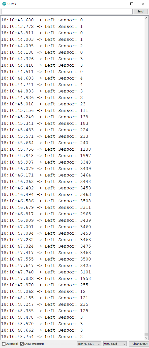
As seen in the serial monitor to the right, the range for the capacitive sensor using a 47k Ohm resistor is about 3,500 starting at 0. This is the perfect range for my sensor because it isn't too high, like in the tens of thousands, but it isn't too low either, like in the hundreds. This way I can get a strong reading of when the sensor is being activated and when it isn't
Soil Hydration Sensor
The making of my hydration sensor was pretty simple. I first made the sensing stick itself and then worked on the code. The harder part out of the two was definitely the coding, especially trying to find resistors that had the range I wanted. I go over how I made the stick below, and I talk about the coding further below.
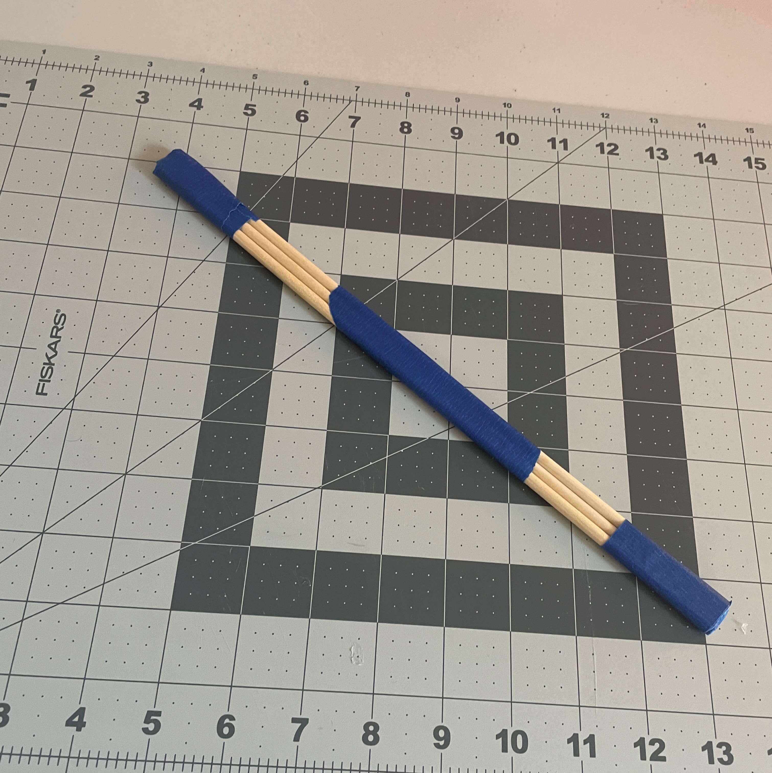
For the sensing stick, I used three wooden dowels and taped them together. I then used aluminum foil as the conductive material for each of the three capacitive sensors. As seen in the middle image, the aluminum foil is laid out in 3 parts: bottom, middle, and top. After that, I started the wiring process. I color-coded my wires so it would be easy to distinguish which wire is coming from which sensor. The black wire is from the bottom sensor, yellow from middle, and red from top. After making this stick, the rest was a bit of breadboard circuitry and coding.
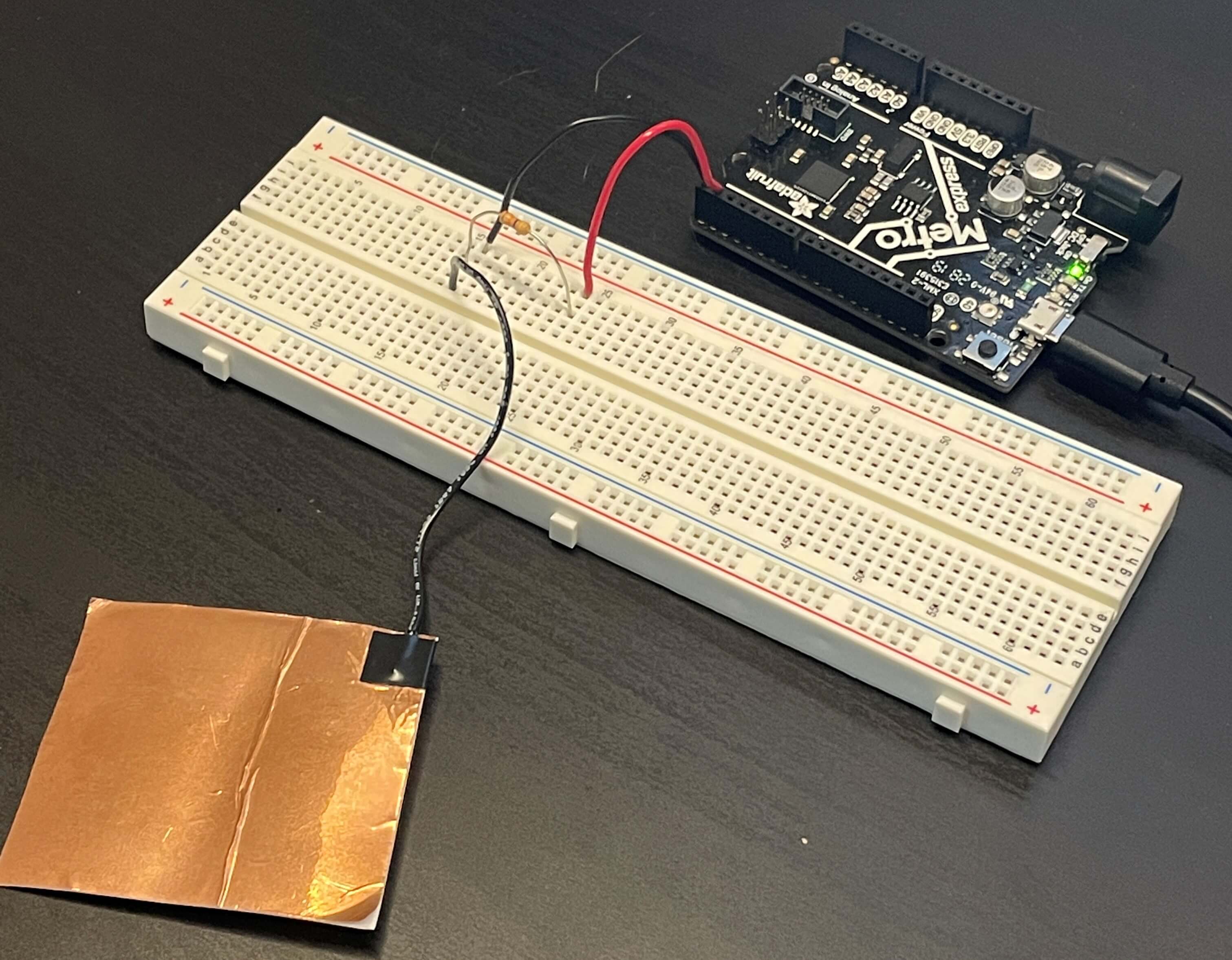
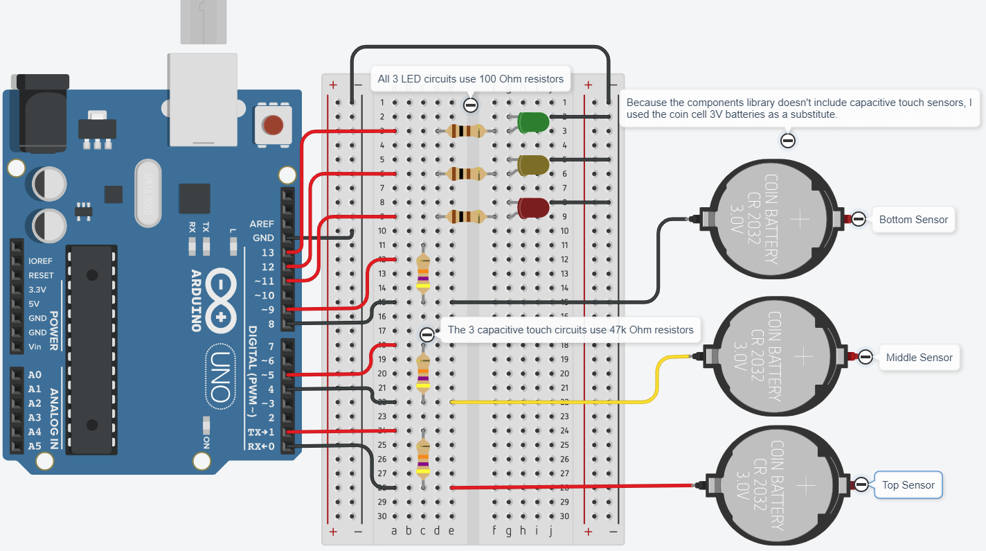
The image on the left shows the final breadboard circuit, including the LEDs. Like I said, each of the capacitive sensor circuits use 47k Ohm resistors, while the LEDs each use 100 Ohm resistors.
The image on the right shows the pin connections. The right 6 pin connections (3 red and 3 black) are for the capactive sensor circuits. For the right 6 wires, the black ones are sensing wires and the red ones are charge wires. For the left 4 wires, the 3 reds are positive for the LED circuits and the black is ground for the whole circuit.
I recreated my circuiit on Tinkercad, as seen below.
One of the key things to note about my code below is that I used the number 150 as an indicator of whether or not the sensor is detecting water. This is because 150 is too high for random sensor fluctuations to accidentally hit, yet low enough for a bit of mousture to trigger the LEDs.
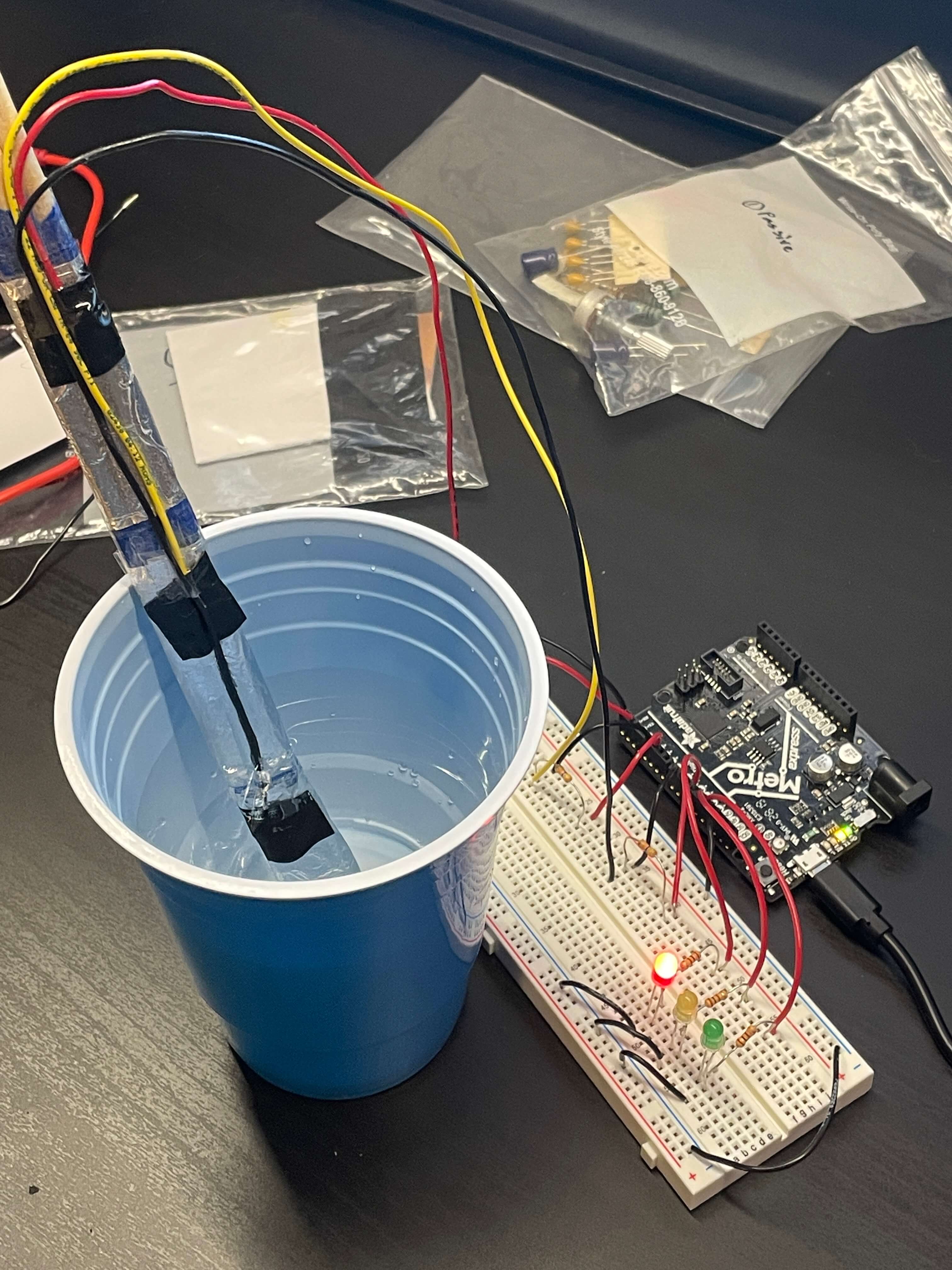
To the left is an image of my makeshift testing setup. I used a blue plastic cup with a bit of water to test the bottom sensor. The reason I didn't individually test all of the sensors is because they all used the same code and were wired the same, so I figured if one worked, they all would.
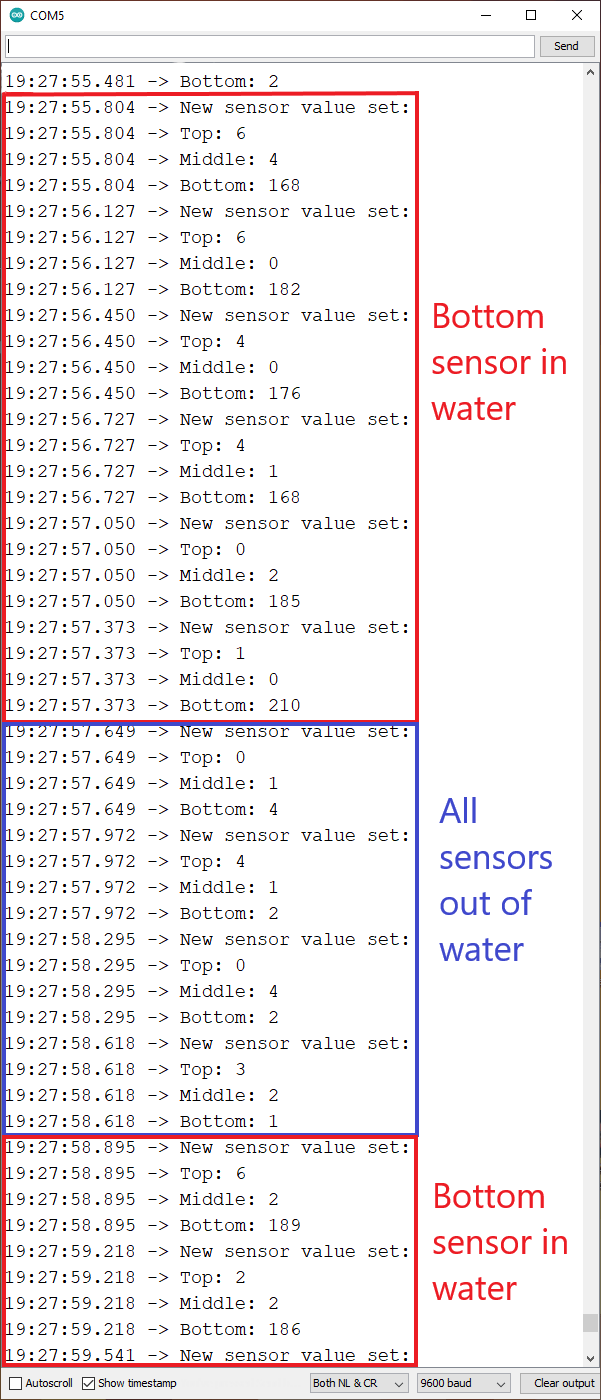
To the right is the serial monitor. In my code, I used the key number of 150 to indicate whether the sensor is detecting moisture or not. So, on the serial monitor, the parts in red have the bottom sensor activates, while the part in blue has no sensor activated as all the numbers are basically 0.
The rest of the code for my sensing stick is pretty simple. I just used the demo that we did and duplicated it three times because I have three sensors. I then hooked up those sensors to LEDs. I have 3 LEDs, signifying good, okay, and not good.
I also added some Serial.print lines to show my sensors working on the serial monitor. This is how I figured out what resistor to use. After that, it was the start of the testing phase.
Below is the serial monitor with markings to show how the serial monitor works. I only used the bottom sensor in my first tests because I didn't want to bring too much water into a cup on my desk scattered with electronics.
My next step was to do a full test. I did this by using a vase and filling it with water, as seen in the first video below.
The second video shows the main problem with my sensor: false readings. Because there is space below the aluminum foil, water can get trapped inside with no way for me to wipe it down. This meant that the water below the foil would trigger the sensors and give false readings. To solve this, I'd either have to make a completely new stick and make it completely waterproof or wait a long time for the stick to dry.
After the first vase test, I moved on to a real planted pot. The same false reading issue still persisted, but I was able to get a fully running test without false readings.
In this test, when I first put the sensing stick in the soil, the red LED lit up, meaning that the pot had water in the bottom. The yellow LED started to blink, which meant that there was a little bit of water. However the green LED wasn't lit, meaning there was no water near the top. I poured some water in onto the area of the sensor (because I didn't want to wait all day for the soil to saturate with water) and it worked great. The lights all stayed lit after I poured in the water, which meant that the sensors were accurately detecting water.
What I Learned
» How to use capacitive sensors as inputs
» How to manually calibrate capacitive sensors using resistors
» How to manually calibrate capacitive sensors using thresholds and maximums
» How to solve basic issues with capacitive sensing